Pages

Senin, 21 Maret 2016

Planking away

Work has slowed a bit as we move into the rainy season here in the Pacific Northwest. Not only are the days getting shorter, colder and wetter, but Im back to working overtime. *sigh*

Nevertheless, Im glad to say that I am making some progress.

Ive got most of the third row of planking on.


Ive fitted the anchor well floor, the front seat, and started fitting the rear side seats. Its a good idea to cut these to size before installing the third row of planking. Its much easier to fit them in place over sized and scribe the outer hull position using a batten then to try and fit them later.


I have learned two valuable lessons this time around:

Lesson #1. Carefully inspect your plywood, no matter how good its supposed to be. After installing part of my starboard plank, I noticed that something looked odd at one of the edges. Closer inspection revealed this:

.
Yikes! About a half inch of the edge of this sheet of plywood didnt get bonded properly. Im using Aquatek BS-6566 marine plywood and Ive built two boats using this stuff, and this is the first time Ive run across a flaw like this.  I had to trim a half inch from the forward edge of one of my planks, which was already installed, to get rid of the bad edge.  Im inspecting every piece from now on.

Lesson#2: When installing the planks, its easy to clamp them along the top edge, but the bottom edge has to be fastened with screws, which are removed after the epoxy cures.  This leaves a line of ugly screw holes that has to be plugged and sanded. I started doing it this way but then I found a better way. Now I use my PowerShot staple & nail gun loaded with 1/2" nails.


This stapler has just enough power to drive these tiny little nails most of the way through a 1/4" sheet of plywood and into the underlying stringer.  To install the plank, I goop the stringers up with "peanut butter", clamp the plank in place along the top, then press firmly along the bottom and drive in a nail every few inches or so.


 The little nails are easily pulled later on with a pair of pliers, leaving just a little pinhole.  The only downside is that the stapler has a tendency to jam but it still beats using screws by a long shot IMHO.
Read More..

Companion way

I still had one more major wood working job left on the lower hull that Ive been blowing off for a few months now, and that was finishing the companion way from the salon to the cabins below. In order to get the 12,000 BTU air conditioner installed along with the associated wiring, I had to get the companion way ( stair way) completed.

This is another busy area of the boat. The DC electric passes from the engine room to the helm via conduit and a junction box in the companion way. This includes the 2/0 cables from the battery bank, the main engine and generator wiring harnesss, the bilge pumps controls, high water alarms controls and whatever other DC wires I can conjure up. I installed six one inch conduits, two 3/4" conduits, and some 1/2" conduits from this junction box to the helm in this tight space.

The 12,000 BTU air conditioner will also reside in the companion way underneath the stairs. This 12000 BTU air conditioner is keel cooled and will be for the sleeping cabins only. Another marine air conditioner is in the lazarette, and will service the wheel house and salon. The stairs you see in these pictures are plywood stairs that Im using for construction. The final stairs will be made from Cherry, and will be closed stringers and risers ( with ventilation). The important part of the stairs you see in these pictures, and along with the final stairs, is that the stairs are hinged for quickly gaining access underneath the stair case. The hinging of the stairs is another one of the things I got right on the build and have proven to be fantastic in regard to getting things done quickly in this area. Along with the air conditioner, the ducts for the forward cabins will rise from the air conditioner via the companion way cabinet on its way to the utility chase that is framed between the ceiling the the hull liner.

The vent and fill manifold for the starboard water tanks are also accessed from behind the companion way cabinets via access panels.

The overboard clothes washing machine discharge piping along with the half bath sink above, and the sump discharge for the air conditioner leave the boat from this area. Just to make things complete, I installed two spare one inch above the water discharge points, and one more 1 1/2" above the water discharge point in this area. All of this is accessed from either underneath the stairs, or from inside the companion way cabinet.

Once you come down the companion way stairs, you land in the area where you either continue straight to the kids cabins dressing room, or you turn left to enter the master cabin. Since the outboard area of this landing was not much use, I decided to add shelves go get more storage. The shelves are fixed and have fiddles fixed to them. I have a vision of these shelves being used for can goods, but time will tell just how they evolve. I know they will need another bar going across the opening to hold things in place, but Ill wait on building that until I see what everyone wants to use them for.

The cabinet on the outboard side of the companion way came about as a way to hide the junction box and air conditioning duct work. I created two shelves in this cabinet plus sunk the bottom of t
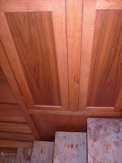
he cabinet to allow storage of large bulky items. This will be a large item cabinet. Because of the hinge stairs, and wanting to keep the stair case width, I built these doors as a flush style vs the overlay style Ive built on the rest of the boat. The flush style is more challenging to build as the door must be fit in to the opening and all the reveals need to be consistent for the door to look good. Since the humidity has been high here lately, I gave these doors a 1/6" reveal. The doors are frame and panel construction using Cherry wood. When all is said and done, and the final stairs are installed, I want no more than a 3/8" gap between the hinged stairs and the companion way cabinet and opposing wall. This is why I went with the flush door method, and is also why Ill have to use drilled finger pulls ( holes ) to open the cabinet doors. I want this area to be easy to navigate down with no snags or things to bump against. I paid particular attention, using a plumb bob and good layout, to make sure these cabinets were square and plumb with the bulkhead that the steps will be hinged to. It is important to me that the steps swing up smoothly and do not rub the cabinets and wall given the tight gaps I want to hold on the casework.

I have two coats of satin urethane on everything so things should be protected for the rest of the build. I can now install the keel cooled air conditioner and check another item off of the list. This was a fairly large wood working job, and I have over a week in getting it completed. The last wood working projects for the lower hull are building of the passage doors and building the finish stairs for the companion way.
Read More..

Didi 950 Projects

There appears to be considerable interest in my posts about the boats being built to our Didi 950 design. This is a radius chine plywood design with hard chine in the topsides, designed to fit into the Classe 950 box rule. In the past few days I have received a bunch of new photos that show the build process clearly, as well as some updated progress photos.

Before going into the new photos, you might like to read the article that I posted today on my Boatbuilder Tips for Amateurs blog about how to construct building stocks or beds, the foundation off which the skeleton of a wooden boat is built. It is illustrated with photos of the Didi 950 that is being built by Fred Grimminck in Australia. The photos below are mostly of that same project, being built from scratch without a kit.

The photo below shows the various backbone components, all of which slot eggcrate-fashion into the bulkheads. The slots help to locate the bulkheads and backbones correctly relative to each other. The bow and stern have single backbone on centreline and the mid-part of the hull as two backbones that run down each side of the keel support box. The two shorter pieces on the right are the paired double-backbone parts. Next toward the left is the aft backbone, which turns up at the far end to support the transom. Extreme left is the bow backbone, which turns up at the far end to form the stem and supports a bow bulkhead into which the forward ends of the stringers are located.
Didi 950 backbone components. Click on all photos to enlarge.
The photos below show a few of the forward bulkheads with the bow backbone dry-fitted in place. The backbone has doublers just below deck level for through-bolting the bow chainplate. The doublers can be seen at the forward lower end of the backbone.
Didi 950 bow backbone and forward bulkheads
Didi 950 bulkheads and backbones
In this next photo, the transom doubler has been set up as a doubler and the stringers etc run through, then are trimmed flush. When the transom is glued over the doubler the end-grain of the longitudinals will be covered and protected. Look through the 4th cutout from left through the doubler to see how the aft end of the aft backbone turns up against the inside face of the doubler. The backbone has locating tabs that slot through the doubler, seen as light-coloured marks on centreline of the doubler. In the lower photo the transom is being glued over the outside of the doubler.
Didi 950 transom doubler
Didi 950 transom being glued over doubler.
The sheer clamps on this design sit diagonally across the corner at the intersection between hull sides and decks. They are screwed and glued to cleats on the faces of all bulkheads. In this photo the sheer clamp is clamped to those cleats. You can also see how the stringers are slotted through the bulkheads. Once the hull skin has been glued on, these junctions become very strong and rigid
Didi 950 sheer clamp
Looking forward along the hull just prior to fitting the bottom skin. The wide stringers on both sides are the tangent stringers, with doublers to back up the joint between flat bottom panels and radius skin panels at the turn of the bilge.  The single aft backbone can be seen running through to the 3rd bulkhead from the bottom of the photo. The double backbone runs forward from the 2nd bulkhead from the bottom of the photo, then changes back to a single backbone further forward, also visible.
Didi 950 bottom stringers and backbones
Stringers in the forward part of the hull, mainly showing the radius area. The two broad stringers are at the tangents, joining the flat and radiused skins together. Between them are three radius stringers, over which the double-skin radius will be formed. Below the lower of the two tangent stringers are the stringers for the side skin panels.
Didi 950 stringers
This last photo shows Mike Vermeeschs boat, being built from a kit in Ohio. Mike has the side panels all dry-fitted to check for fit ahead of gluing in place. Looks like a nice fit. The bow will be capped with solid wood, which will cover and protect the end-grain of the stringers.
Didi 950 hull side panels
Thank you to both Fred Grimminck and Mike Vermeersch for taking the trouble to send me these photos and allowing their use.

To see our other designs, please visit http://dixdesign.com/ .
Read More..

Minggu, 20 Maret 2016

Cape Henry 21 Launched in Croatia

Dean Ivancic lives in Porec, Croatia. He bought plans from us a few years ago for the Cape Henry 21. He has been working steadily on his boat and reported to me today that he launched her in April. He has sent me some rather nice photos of her under sail. She is still incomplete down below but has all that is needed to sail.

She is named "Scintilla", Italian for "spark", also the meaning of "Iskra", the Croatian name of Deans youngest daughter.

We wish Dean and his family lots of fun and adventures in their Cape Henry 21.
"Scintilla" on one of her first outings.
Pretty from any angle.
Dean has done a nice job of building "Scintilla".
The Cape Henry 21 is surprisingly quick and has delightful manners. These boats prove that a boat doesnt have to be ugly to be fast.

For more on this design and others in our range, go to http://dixdesign.com/.
Read More..

Clothesline Anchoring Revisited

Lately, on the jwbuilders forum, there has been some discussion about how to do a clothesline anchoring system. There are several ways to do it - some are simple, some complex.
This is my favorite method:

 
  1. Tie one end of the anchor line to the bow cleat.
  2. Run the anchor line through a ring on the end of the anchor chain.
  3. Tie the other end of the anchor line to the stern cleat.
  4. Drop the anchor a bit offshore.
  5. Move the boat close to shore, to knee deep water or right to the beach.
  6. Step out, grab the shore anchor and the anchor line loop and take them ashore.
  7. Bury the shore anchor in the beach and tie the anchor line to it as shown below.  Or tie to a log or tree.
  8. To reel the boat in and out, untie, pull one side of the anchor line loop or the other, and retie.
Tie the anchor line to the shore anchor
Notes:
  • Securely tie the anchor line to your shore anchor as shown.  That way, if your other anchor were to slip or the anchor line were to break, you would not lose the boat because it would still be attached to the shore anchor.
  • The boat can be oriented with the bow pointed to shore or the stern. The system works either way. You can even change the direction later if you prefer.
  • You need plenty of anchor line since were forming a long loop.
  • I prefer a sinking line over floating to prevent someone cutting it with their prop.
  • I recommend using large, smooth stainless steel rings instead of blocks on the end of the anchor chain to prevent them from jamming with rocks, sand or seaweed.
  • There is no need for an anchor chain on the shore anchor 
  • This is a short-term anchoring solution. Do not rely on it for long-term moorage.
  • If you sleep onboard your boat: 1) loop the anchor line through a ring on your shore anchor instead of tying it. 2) Keep the loop onboard (the length of anchor line lying on the bottom under the boat) so you can use it to pull yourself to and from shore. Cleat it to prevent the boat from reeling itself in or out. 3) Youll need an even longer anchor line since youll reside further offshore and will still want to maintain scope on your anchor.
Read More..

Polaris by Sam Rabl


Sam Rabl is one of my favorite designers. Especially his designs for home builders. If youve been around here for a while, you may remember that my first fixed keeled boat was a Picaroon designed by Sam.


A Doryman reader wrote to me a while back to remind me that Sam Rabl also designed a slightly bigger boat built in plywood called a Polaris. He also had some questions about details, so I asked another faithful reader, whos an excellent historian, to do some research.


We are talking about a seaworthy boat here and even though Sam claims you can build it in your backyard does not mean its simple. This is a boat for a serious sailor and will take you anywhere you want to go.


But first youll have to pick your sail rig. Here we have no less than four options, including a hermaphrodite brig.


Die Pläne und Offsets finden Sie hier:
A timeless design. The 24 foot Polaris.


Read More..

More wheel house

I should probably start by saying Im going to stop crying about the winter that wont end. I know its close to giving up the beast, but after the 6" storm we had two days ago, and lows in the single digit this week, its fighting to the bitter end. The high today was around 26 degree F, but with the sun gathering strength, the cold air temperature can no longer sustain the snow, and its quickly receding. Given the air temperature is still below freezing cold, having the boat facing south, along with the strengthening sun, heats the inside of the boat up quickly, and I really dont have to run the heater at all.

I finished trimming the windows, and also got some color on the wood. The window trim is basically a house style detail being a 1/2" x 2 3/4" casing, a 3/4" x 2 1/4" stool, and a 1/2" x 2 3/4" bonnet under the stool. All the reveals are a 1/4".  Its a simple look, but I think its legitimate.  

Some more progress has been made in the wheel house, and Im inching up on getting the wood work completed. The layout was finalized, and more compromises were made. We were pretty dead set on having a 240 volt clothes drying machine and a 120 volt clothes washer, but in the end, having two units just took up too much space. In the space where the clothes dryer was going to go, I built a base cabinet with two large  drawers, and two doors underneath. Because the drawers are so wide, I used 3/8 plywood for the bottoms vs the usual 1/4". Im planning on the drawers being used for paper charts and other things navigation.  The drawer fronts are not installed yet as I just  fitted the boxes in place.
 
Just aft of the new base cabinet is the opening for the compact LG washer/dryer combo unit. Out of all the units I looked at on line, the LG units have the best, most consistent reviews. Im a little leery of its ability to dry clothes with only 120 volts, so I have it in the back of my head that a decent working clothes line might be in order... probably something on the roof running off of the mast.

The large opening starboard of the instrument dash area is where the electrical distribution panel  is going to go. I had some sort of cut twice/measure once thing going on and screwed up the door that houses the electric panel. I found out this mistake today as I was fitting all the shiny parts Ive made in the last week.

I have the wheel house counter top fabricated and dry fitted in place, but not not yet installed. Before the top gets installed,  I need to land all the wires on the bulkhead behind the distribution panel door. I used THHN for the primary wiring behind the walls, and will land all that on terminal strips. From the terminal strips, to the distribution panel, Im using a flexible, tinned, marine wire. I have about 90% of the boat wire pulled to the area under the dash, and landing it with the top off is going to be  huge vs lying on my back. I realize Ill still be doing some wiring while laying down, but I want to get as much done while its relatively accessible.

While I was fabricating in the barn last week, I decided to make the panel that finishes covering the dry exhaust/intake stack. Because the stack is such a large fixture, I decided to make this panel a raised panel. A large, flat piece of plywood just didnt feel right. The cherry veneer plywood is for sure nice material, but in my opinion, is a little too perfect. The air dried cherry I am using oozes character, and really puts the plywood to shame in regard to interest.  Being in the center of the room and such a visual element, this large raised panel looks spot on.

Heres to the coming Spring.

Cheers


Read More..